
Thermal Flow Meter TGF410 – Air and Nitrogen
TGF410 is a thermal mass flow meter for air and nitrogen, built as the economical model in the thermal range for indoor use. It measures mass flow directly from the heat taken away by the moving gas, so it reports flow in normal cubic metres per hour without a separate pressure or temperature correction in normal use. It is aimed at plants that need a reliable gas flow reading for compressed air and nitrogen inside a building, without paying for the wider gas list, the larger pipe range and the higher protection rating of the other thermal models.
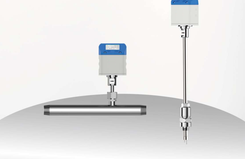
TGF410 starts to measure at 0.3 Nm/s and reaches 180 Nm/s in its widest band, covering most industrial gas lines. A 2 inch TFT display can turn through 180 degrees, and readings can be recorded and exported through a phone app. It responds in about 1 second, and a self-check flags a fault instead of letting a bad reading pass.
Features
- Direct mass flow measurement – reports flow in Nm3/h without a separate pressure or temperature correction in normal use.
- Low-cost economical model – the most cost-effective thermal meter for indoor air and nitrogen.
- Wide velocity range, 0.3 to 180 Nm/s, in six bands; the default band is 0.9 to 90 Nm/s.
- No pressure loss; the insertion form fits pipes DN25 to DN400 and supports hot tapping on a live line.
- Compact indoor design – PC and ABS plastic enclosure, IP65; for indoor use only.
- 2 inch TFT display that turns through 180 degrees; readings recorded and exported through a phone app.
- Fast response, about 1 second, with self-check that flags a fault instead of letting a bad reading pass.
- Pulse, 4 to 20 mA, RS485, HART and Bluetooth outputs.
TGF410 works on the thermal mass principle: two sensing elements sit in the gas stream, one heated and one measuring gas temperature. Extra power holds the heated element at its set temperature, and that power rises with mass flow. The meter turns that power into direct mass flow in normal cubic metres per hour, at 20 °C and one atmosphere.
The fluid list for this model needs a careful note. The specification table lists air and nitrogen as the fluids, while the applications list in the same chapter also names carbon dioxide, argon and helium. A buyer who wants to measure carbon dioxide, argon or helium should confirm with the supplier that the meter is set up for that gas before ordering — do not assume the air and nitrogen setting will read another gas correctly.
TGF410 fits indoor gas systems in factories, workshops and process plants. It suits compressed air networks inside a building, showing how much air each area uses and where air is being lost, and nitrogen supply lines, where a steady mass flow reading is needed for control and accounting. It is listed for indoor use only, with an IP65 enclosure rather than IP67, so it is not the right choice for a meter that will stand out in rain or washdown.
The insertion form is the most flexible, fitting pipes from DN25 to DN400 (1 to 16 inches). It also supports hot tapping, so it can be fitted to a live line through a tapping valve without shutting the line down, following the site’s hot tapping procedure. The flanged form covers DN25 to DN300, and the threaded form DN32 to DN50 for small lines. There is no wafer form for this model. The meter is built for indoor plant conditions. Its enclosure is PC and ABS plastic rather than aluminium, its display cover is PA with 15 percent glass fibre, and its ambient range is minus 20 to 60 °C. Fluid temperature is minus 40 to 150 °C, so it covers cold gas and warm compressed air, but it is not a steam meter — steam service belongs to the larger TGF680.
Specification
Measurement range
Six velocity bands are listed; the band is chosen when the meter is ordered. The bands are 0.3 to 30, 0.6 to 60, 0.9 to 90, 1.2 to 120, 1.5 to 150 and 1.8 to 180 Nm/s, with 0.9 to 90 Nm/s as the usual default. A low band suits a line that runs gently; a high band suits a line that can surge.
The table below gives the normal volume flow range for the default 0.9 to 90 Nm/s band, at 20 °C and one atmosphere.
| PIPE SIZE | MINIMUM FLOW, NM3/H | MAXIMUM FLOW, NM3/H |
|---|---|---|
| DN25 (1 in) | 1.59 | 158.9 |
| DN32 (1.25 in) | 2.60 | 260.3 |
| DN40 (1.5 in) | 4.07 | 406.8 |
| DN50 (2 in) | 6.36 | 635.6 |
| DN65 (2.5 in) | 10.74 | 1,074.2 |
| DN80 (3 in) | 16.27 | 1,627.1 |
| DN100 (4 in) | 25.42 | 2,542.4 |
| DN125 (5 in) | 39.72 | 3,972.5 |
| DN150 (6 in) | 57.20 | 5,720.3 |
| DN200 (8 in) | 101.69 | 10,169.5 |
| DN250 (10 in) | 158.9 | 15,889.8 |
| DN300 (12 in) | 228.81 | 22,881.4 |
For other velocity bands, flow scales with velocity: the lowest band, 0.3 to 30 Nm/s, gives one third of the values in the table, and the highest band, 1.8 to 180 Nm/s, gives twice the values.
Specification of TGF410 thermal mass flow meter
| Item | TGF410 |
|---|---|
| Fluid, specification table | Air and nitrogen |
| Display | 2 inch TFT LCD display, can rotate 180 degrees |
| Pipe size, insertion | DN25 to DN400 (1 in to 16 in) |
| Pipe size, flanged | DN25 to DN300 (1 in to 12 in) |
| Pipe size, threaded | DN32 to DN50 (1.25 in to 2 in) |
| Velocity range | 0.3 to 180 Nm/s, in six bands; 0.9 to 90 Nm/s is the default |
| Pressure, insertion and threaded | 16 bar (232 psi) |
| Pressure, flanged | 16, 25 or 40 bar |
| Flange standards | DIN PN16, PN25 or PN40; JIS 10K or 20K; ANSI Class 150 or 300 |
| Outputs | Pulse, 4 to 20 mA, RS485, HART over 4 to 20 mA and Bluetooth |
| Fluid temperature | Minus 40 to 150 °C (minus 40 to 302 °F) |
| Accuracy | 1.5 percent of reading plus 0.5 percent of full scale |
| Repeatability | One third of the accuracy figure |
| Response time | 1 second |
| Power supply | 16 to 32 V DC |
| Ambient temperature | Minus 20 to 60 °C |
| Protection | IP65, indoor use only |
| Materials | Sensor 316L; probe 304, 316L optional; bore 304, 316L optional; enclosure PC plus ABS; display cover PA with 15 percent glass fibre |
Accuracy is 1.5 percent of reading plus 0.5 percent of full scale — best at high flow, less good at low flow.
Dimensions
The catalog gives insertion probe dimensions and threaded connection dimensions for the TGF410. Probe length sets how far the sensor reaches into the pipe, and overall length is probe length plus the transmitter head. For the threaded form, height H1 is measured from the pipe centre to the top of the transmitter. No bore length table for the flanged form is printed, so the figures below are the insertion and threaded dimensions, with inches worked out from millimetres at 25.4 mm to the inch.
| Insertion probe length | Overall length | Pipe size |
|---|---|---|
| 255 mm (10.04 in) | 360 mm (14.17 in) | DN25 to DN150 (1 in to 6 in) |
| 320 mm (12.60 in) | 425 mm (16.73 in) | DN25 to DN250 (1 in to 10 in) |
| 395 mm (15.55 in) | 500 mm (19.69 in) | DN25 to DN400 (1 in to 16 in) |
| Threaded pipe size | Thread | Height H1 |
|---|---|---|
| DN32 (1.25 in) | R 1 1/4 in | 217 mm (8.54 in) |
| DN40 (1.5 in) | R 1 1/2 in | 217 mm (8.54 in) |
| DN50 (2 in) | R 2 in | 247 mm (9.72 in) |
Choose the shortest probe that reaches the right depth in the pipe: too short will not sit in the main stream.
Model selection
When ordering, give the fluid, velocity band, process connection, wetted materials, transmitter form, output, power supply and pipe size. The table below lists the choices for each item.
| Selection | Options |
|---|---|
| General model | TGF410 – Standard |
| Fluid | Air and nitrogen; carbon dioxide, argon and helium only after confirming with the supplier |
| Measurement velocity | 0.3 to 30 Nm/s (option); 0.6 to 60 Nm/s (option); 0.9 to 90 Nm/s (standard, default); 1.2 to 120 Nm/s (option); 1.5 to 150 Nm/s (option); 1.8 to 180 Nm/s (option) |
| Process connection | Insertion, DN25 to DN400, probe 255, 320 or 395 mm; Flanged, DN25 to DN300, DIN PN16, PN25 or PN40, JIS 10K or 20K, or ANSI Class 150 or 300; Threaded, DN32 to DN50, R 1 1/4, R 1 1/2 or R 2 |
| Wetted materials | Sensor 316L; probe 304 (316L optional); bore 304 (316L optional) |
| Transmitter output | Pulse and 4 to 20 mA; RS485; HART over 4 to 20 mA (optional); Bluetooth |
| Power supply | 16 to 32 V DC |
| Pipe size | Give the pipe size when ordering: insertion DN25 to DN400; flanged DN25 to DN300; threaded DN32 to DN50 |
Confirm the full ordering code against the COMATE 2026-2027 catalog, thermal mass flow meter chapter, pages 38 to 41, before ordering.
Document
The meter is described in the COMATE 2026-2027 catalog, thermal mass flow meter chapter, pages 38 to 41, where the full measuring range and ordering code tables are printed. This page gives the main figures from that chapter in summary form. Compared with the TGF460, it is the lower-cost choice for indoor air and nitrogen service; compared with the TGF680, it is a simpler meter for ordinary gas temperatures up to 150 °C and flows up to 180 Nm/s.
Related flow meters
- Thermal Flow Meter TGF680 – the larger thermal model for gas and steam, up to 240 Nm/s and 450 °C.
- Thermal Flow Meter TGF460 – the economical thermal model for air, nitrogen, oxygen and carbon dioxide, up to 180 Nm/s.
- Thermal Flow Meter TGF260 Micro – the small threaded thermal meter for DN15 to DN25 gas lines.
- Flow Meter – the Flow Meter hub page, with the vortex flow meter range.
- Vortex Flow Meter VFM60 – a vortex meter for gas, steam and liquid in the same Flow Meter range.