
Vortex Flow Meter VFM60 – Gas, Steam and Liquid
The Vortex Flow Meter VFM60 is a multi-variable vortex meter built for gas, steam and liquid service. It covers all three media in one instrument, so one meter type can serve a compressed air line, a steam header and a water or process liquid line. In its VFM60MV form it measures temperature and pressure in the meter itself, for compensated mass flow for steam and gas – without separate pressure and temperature transmitters and extra wiring.
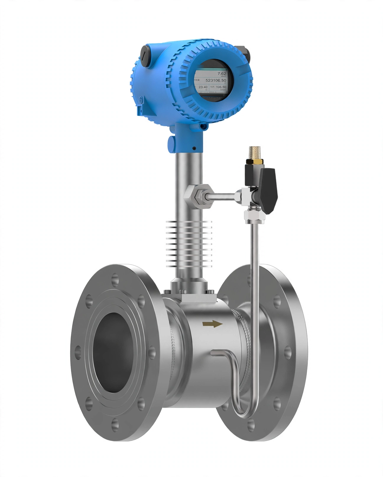
It works on the vortex shedding principle: a bluff body sheds vortices alternately from each side, and the shedding rate rises with flow velocity. The meter counts that rate, with no moving parts in the stream to wear – well suited to steam and gas lines where flow swings widely. Because pressure and temperature change the density of steam and gas, the VFM60MV combines temperature and pressure compensation to calculate mass flow directly.
Features
- One meter for gas, steam and liquid – a single meter type for compressed air, steam and process liquid lines.
- Multi-variable VFM60MV form measures flow rate, temperature and pressure in one instrument, and calculates density and mass flow without a separate sensor or a flow computer.
- High sensitivity, with minimum flow down to 2 m/s, and a wide turndown – 1:35 for steam, 1:30 for gas, 1:22 for liquid.
- Dual-sensor design for anti-vibration (0.5 g), keeping readings steady near vibrating equipment.
- No moving parts in the stream, and very small pressure loss.
- 2 inch TFT display showing flow, total and measured process values.
- Pulse and 4-20 mA outputs, with RS485, HART and Bluetooth.
- Bluetooth operation for parameter setting, flow signal and data analysis, and remote diagnosis through the Comate Bluetooth app.
- Password protection and self-diagnosis built in; free air delivery (FAD) measurement available for compressed air.
Specification
Measurement range
| Medium | Minimum velocity | Maximum velocity |
|---|---|---|
| Gas | DN15-DN20: 6 m/s; DN25-DN32: 4 m/s; DN40-DN300: 2 m/s | 60 m/s |
| Steam | DN15-DN20: 6 m/s; DN25-DN32: 4 m/s; DN40-DN300: 2 m/s | 70 m/s |
| Liquid | 0.3 m/s | 7 m/s |
Check sizing against the real flow at normal and low load, not only the pipe size – a meter in too large a line will read nothing at low flow.
Specification of VFM60 series vortex flow meter
| Item | VFM60 detail |
|---|---|
| Process connection | Flange or wafer, DN15 to DN300 (1/2 to 12 inches) |
| Body styles | Wafer and flanged |
| Nominal sizes | DN15 to DN300 (1/2 to 12 inches), both styles; flanged in mode codes to DN400 (16 inches); larger sizes on custom order |
| Flange standards | DIN PN16, PN25, PN40, PN63; JIS 10K, 20K, 30K; ANSI Class 150, 300, 400 |
| Medium temperature | Standard -40 to 150 °C; medium -40 to 250 °C; high -40 to 350 °C |
| Fluid pressure | Up to 16 Bar wafer; 16, 25, 40 or 63 Bar flanged, matching the flange rating |
| Flow accuracy | Gas and steam ±1% of reading (Re ≥ 20000), ±2% of reading (10000 < Re < 20000); liquid ±0.75% of reading (Re ≥ 20000), ±2% of reading (10000 < Re < 20000) |
| Pressure accuracy | ±0.5% of full scale |
| Temperature accuracy | ±1.0 °C, or ±1% of full scale above 100 °C |
| Turndown ratio | Gas 1:30; steam 1:35; liquid 1:22 |
| Repeatability | Volume and mass flow ±0.3%; temperature ±0.05 °C; pressure ±0.05% of full scale |
| Straight run | 15 × D upstream; 5 × D downstream |
| Viscosity allowance | DN15 ≤ 4 mPas; DN25 ≤ 5 mPas; DN40-DN300 ≤ 7 mPas |
| Anti-vibration | 0.5 g |
| Display | 2 inch TFT, showing flow, total and measured process values |
| Outputs | Pulse and 4-20 mA; RS485, HART and Bluetooth |
| Communication | HART (V5, V7), Modbus-RTU, Pulse |
| Power supply | 4-20 mA, 2-wire, 13.5-42 V; VFM60MV with 4-20 mA (2-wire) 15.5-42 V; Modbus RTU 13.4-42 V |
| Ambient temperature | -20 to 60 °C |
| Protection | IP65 and IP67 |
| Saturated and superheated steam measurement | Supported |
| Explosion proof | NEPSI Ex d II c T3 Gb |
The VFM60 fits steam supply and condensate return, compressed air and industrial gas distribution, boiler feed and process water, and general liquid metering. The multi-variable version is the natural choice for steam mass flow and for gas where line pressure varies. Install it with a straight run upstream and downstream, the line full and the flow steady.
Model selection
| Selection | Code | Description |
|---|---|---|
| Model | VFM60N | Standard digital vortex |
| Model | VFM60MV | Multivariable vortex |
| Model | VFM60I | Insertion vortex |
| 1 Fluid type | G | Gas (standard) |
| 1 Fluid type | S | Steam (option) |
| 1 Fluid type | L | Liquid (option) |
| 2 Process connection | F | Flanged (standard) |
| 2 Process connection | W | Wafer (option) |
| 3 Wetted part material | S | SS304 (standard) |
| 3 Wetted part material | H | SS316 (option) |
| 3 Wetted part material | HC | Hastelloy C (option) |
| 4 Degreased | N | No (standard) |
| 4 Degreased | Y | Yes (option) |
| 5 Medium temperature | S | Standard -40 to 150 °C (standard) |
| 5 Medium temperature | M | Medium -40 to 250 °C (option) |
| 5 Medium temperature | H | High -40 to 350 °C (option) |
| 6 Transmitter | A | 4-20 mA, 2-wire (standard) |
| 6 Transmitter | B | 4-20 mA, 2-wire + RS485 (option) |
| 6 Transmitter | C | Pulse (option) |
| 6 Transmitter | D | 4-20 mA, 2-wire + HART (option) |
| 7 Cable gland | G1/2 in | Standard |
| 7 Cable gland | M20 x 1.5 | Option |
| 8 Ex-proof | N | No (standard) |
| 8 Ex-proof | Y | Yes (option) |
| 9 Pipe size | DN15-DN300 | Standard |
| 9 Pipe size | DN350-DN400 | Option |
Flanged sizes are also available in mode codes to DN400 (16 inches); larger sizes are available on custom order.
ANSI flange dimensions
Dimensions from the VFM60 manual Rev 1.8, p.51.
ANSI Class 150
| Size | K Flange O/D | L Pipe length | W Bolt-circle | C Flange thickness | M Screw-hole diameter | N Screw qty | H Meter height 150 °C | H Meter height 250 °C | H Meter height 350 °C |
|---|---|---|---|---|---|---|---|---|---|
| DN15, 1/2 in | 88.9 | 160 | 60.5 | 11.1 | 15.5 | 4 | 273 | 295 | 323 |
| DN20, 3/4 in | 98.6 | 160 | 69.9 | 12.7 | 15.5 | 4 | 278 | 300 | 328 |
| DN25, 1 in | 108 | 160 | 79.2 | 14.3 | 15.5 | 4 | 286 | 308 | 336 |
| DN32, 1-1/4 in | 117.6 | 190 | 88.9 | 15.9 | 15.5 | 4 | 295 | 317 | 345 |
| DN40, 1-1/2 in | 127 | 190 | 98.6 | 17.5 | 15.5 | 4 | 303 | 325 | 353 |
| DN50, 2 in | 152.4 | 190 | 120.7 | 19.1 | 19.1 | 4 | 316 | 338 | 366 |
| DN65, 2-1/2 in | 177.8 | 220 | 139.7 | 22.2 | 19.1 | 4 | 330 | 352 | 380 |
| DN80, 3 in | 190.5 | 240 | 152.4 | 23.9 | 19.1 | 4 | 351 | 373 | 401 |
| DN100, 4 in | 228.6 | 280 | 190.5 | 23.9 | 19.1 | 8 | 393 | 415 | 443 |
| DN125, 5 in | 254 | 300 | 215.9 | 23.9 | 22.2 | 8 | 409 | 431 | 459 |
| DN150, 6 in | 279.4 | 320 | 241.3 | 25.4 | 22.2 | 8 | 426 | 448 | 476 |
| DN200, 8 in | 342.9 | 340 | 298.5 | 28.6 | 22.2 | 8 | 459 | 481 | 509 |
| DN250, 10 in | 406.4 | 400 | 362 | 30.2 | 25.4 | 12 | 518 | 540 | 568 |
| DN300, 12 in | 482.6 | 440 | 431.8 | 31.8 | 25.4 | 12 | 557 | 579 | 607 |
ANSI Class 300
| Size | K Flange O/D | L Pipe length | W Bolt-circle | C Flange thickness | M Screw-hole diameter | N Screw qty | H Meter height 150 °C | H Meter height 250 °C | H Meter height 350 °C |
|---|---|---|---|---|---|---|---|---|---|
| DN15, 1/2 in | 95.3 | 160 | 66.5 | 14.3 | 15.5 | 4 | 273 | 295 | 323 |
| DN20, 3/4 in | 117.6 | 160 | 82.6 | 15.9 | 19.1 | 4 | 278 | 300 | 328 |
| DN25, 1 in | 124 | 160 | 88.9 | 17.5 | 19.1 | 4 | 286 | 308 | 336 |
| DN32, 1-1/4 in | 133.4 | 190 | 98.6 | 19.1 | 19.1 | 4 | 295 | 317 | 345 |
| DN40, 1-1/2 in | 155.4 | 190 | 114.3 | 20.6 | 22.2 | 4 | 303 | 325 | 353 |
| DN50, 2 in | 165.1 | 190 | 127 | 22.2 | 19.1 | 8 | 316 | 338 | 366 |
| DN65, 2-1/2 in | 190.5 | 220 | 149.4 | 25.4 | 22.2 | 8 | 330 | 352 | 380 |
| DN80, 3 in | 209.6 | 240 | 168.1 | 28.6 | 22.2 | 8 | 351 | 373 | 401 |
| DN100, 4 in | 254 | 280 | 200.2 | 31.8 | 22.2 | 8 | 393 | 415 | 443 |
| DN125, 5 in | 279.4 | 300 | 235 | 35 | 22.2 | 8 | 409 | 431 | 459 |
| DN150, 6 in | 317.5 | 320 | 269.9 | 36.6 | 22.2 | 12 | 426 | 448 | 476 |
| DN200, 8 in | 381 | 340 | 330.2 | 41.3 | 25.4 | 12 | 459 | 481 | 509 |
| DN250, 10 in | 444.5 | 400 | 387.4 | 47.8 | 28.6 | 16 | 518 | 540 | 568 |
| DN300, 12 in | 520.7 | 440 | 450.9 | 50.8 | 31.8 | 16 | 557 | 579 | 607 |
Also in this range: the Vortex Flow Meter VFM80 for a larger velocity range on gas and steam, the Vortex Flow Meter VFM55MV Micro and Vortex Flow Meter VFM52MV Micro for small gas-only lines, and the VFM60MV flanged 150C overview.
Document
- VFM60 Series Datasheet (PDF, Comate)
ANSI flange dimensions above are taken from the VFM60 manual, Rev 1.8, p.51.
If you are unsure which size or temperature version fits your line, check the figures above first, or contact KBS Industries.